Many people are not aware that Rhinoceros is able to generate 2D technical drawings of its 3D models. Well it can; although one should not expect it to be fully associative that are similar to those generated from parametric CAD programs such as Solidworks, Solid Edge, Autodesk Inventor and Creo. Nevertheless, Rhino 3D does offer competent 2D Drafting capabilties.
Rhino Version 6 Demo
Below video shows a demo of this capabilty in version 6 of Rhino
Rhino Version 5 Tutorial
The steps as described below illustrates a typical 2D Technical Drawing creation process of a Rhino 3D Model. For this tutorial, we will show the generic workflow of creating a 2D drawing of a 3D model using version 5 of Rhinoceros 3D. For this tutorial to be understandable, one should have a basic proficiency in using this 3D program.
Please note that the generation of 2D Technical Drawings works best with NURBS models. Mesh or Polygonal 3D models may not be able to produce desirable outputs as it will create mesh edge lines in the 2D drawings.
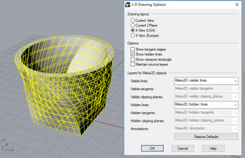
With the 3D Object selected, go to File >> Dimension >> Make 2D-Drawing.
Select the appropriate options from the dialog box. In this example, we used 4 view USA as the Drawing Layout. If you want to display Hidden Line, have the option enabled.
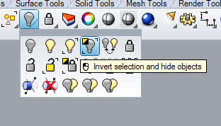
Click OK. The 2D Drawing will be created and will be lying flat on the Cplane (aka Construction Plane) of the Perspective View. With the freshly-created drawings still selected, execute Invert Hide to only display the drawings lines.
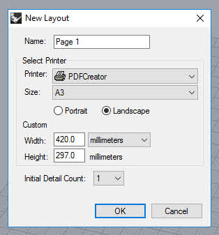
Next, we need to create a new Page Layout. To do that, go to Edit >> Layout >> New Layout.
Set the options. It should be noted that the Initial Detail Count should be set to 1. For the Printer Option, select the an installed PDF creation software. In this example, we will the PDF Creator which is a free alternative to Adobe Acrobat.
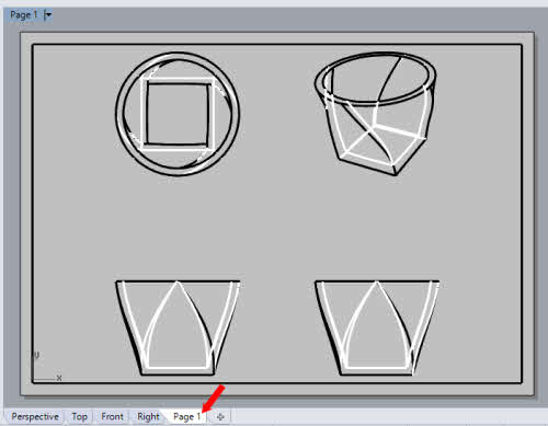
Click Ok. This will create a New Page Layout as shown below.
We have come to the end of Part 1 of this tutorial. Hope that the steps has been clear to you so far.


