
This is Part 2 of the Rhino 3D Tutorial: Making 2D Technical Drawing Using Rhino 3D. As mentioned in Part 1 of this tutorial, this tutorial works best with NURBS models. Mesh models may give undesirable results.
>>> Click here to go back to Part 1
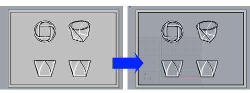
In Part 1, we have created the new page layout that is displaying the orthographic and perspective views of the Rhino 3D Model.
Now, double-click in the page layout region. The layout view now become editable. This is as illustrated in the Rhino screenshots below.
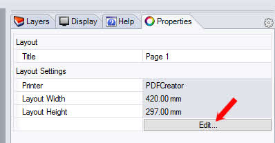
Next, we need to set the drawing to an appropriate drawing scale. To do that, click on the Edit button on the Properties tab that is displaying the info of the New Page Layout.
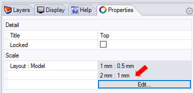
Using the command prompt, set the desired Scale ratio.
When prompted Distance on Layout, key in ‘1’.
Next, when prompted ‘ …. on layout = Distance in model (…)‘, key in the desired value. This should ideally be a rounded-off value.

Once done, double-click the page layout region to exit the Editing mode. The new scale will be reflected at the Properties Tab. This is as shown below.
The Layer window allows the line type and Print width of the 2D Technical Drawing to be set. To make changes, click on the parameter to change.
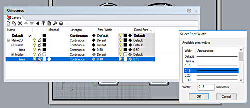
It should be noted that any change to Print Width will be not visible on screen. The result can only be seen in a physical printout.
>>> Click here to go to Part 3 of this Rhino 2D Drawing Tutorial.