
Unlike general 3D modeling, product and industrial design CAID modeling must be precise and accurate. This is to ensure that the built model can be used for 3D printing feasibility evaluation, eventual tooling and mould making for production.
For these reasons, if you are building 3D models that are for plastic parts to be injection molded, you will need to build draft angles into the side surfaces. This is to allow the part to be able to be injected from the mold.
In this tutorial, we will talk about building surfaces that have draft angles incorporated.
Update: Here is a video demonstration pertaining to Rhino 6
For those with older version of Rhino 3D, below is the step by step process using older version’s screenshot.
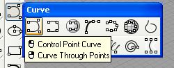
When building curves for the side surface of the part, use Control Point Curve. See screen shot below.
We need to input the draft angle degree. In this case, I want to create a curve that is drafted at 5 degree. After clicking the First Point for the curve, the command line will prompt you for the Next Point. For this, enter (in the command line) “<85”. See the screen shot below.
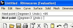
Why 85?. This is because 90-5 = 85. You will now notice that the curve is aligned and constrained to 85 degree. Click on the next point.

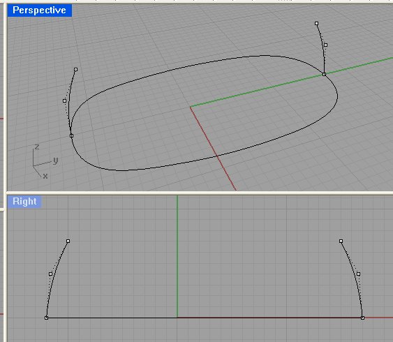
Now, click a 3rd point to complete the curve. Make sure that the 3rd point is on the correct side of the 85 degree alignment.
Once done, build your other drafted curves in this manner. See screen shot below for result.
This concludes Part 1 of these product design modelling tutorial.