
This is Part 2 of the Rhino 3D Building drafted surfaces tutorial. Click here to go to Part 1
In Part 1, we have created the basic drafted curves as shown below.
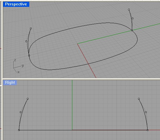
Now, we need to create surfaces from these curves. For different situations, we will need to use different types of surfacing tools. In this case, we will use the Sweep 1 Rail.

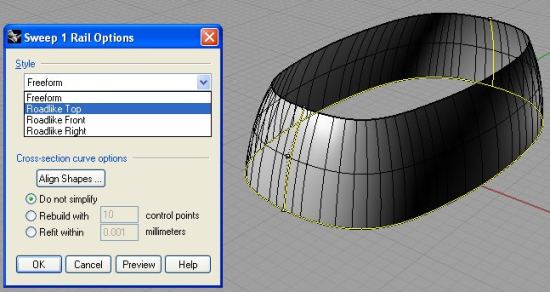
Below shows the surface being built from selecting the closed curve as the Rail and the 2 side curves as the sections. Under the Style section of the dialog box, select the right style based on the orientation of the surface. In this case, I select Roadlike Top to align the new surface to the Top View.
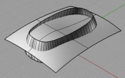
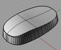
Next build the remaining surface. In this case, I use loft to build a top surface. Next, I use Trim to remove the excess portions of the surfaces. See the next 2 screen shots for a clear understanding.
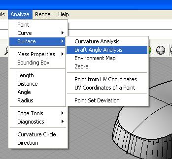
Please understand that there is no full guarantee that the side surface will be correctly drafted. To be on the safe side, we should do a Draft angle analysis. We can access the tool from Selecting Analyze (Menu bar) >> Surface >> Draft Angle Analysis. See the screen shot for a better picture.
Well, this concludes this Rhino 3D tutorial for industrial design surface modeling.
As mentioned, there is no 100% guarantee that the surface will be fully drafted according to the specific angle on all areas. For better security, please do the necessary surface and draft angle analysis.
If you are only building an appearance model, being fully drafted is not so critical. However, if as an Industrial Designer, you are building something that will eventually be the base file for tool making and manufacturing, being precise and fully drafted are of utmost importance.
Thank you for reading.